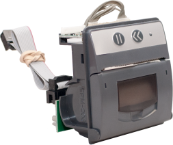
Overview
The XT+ Extinguishant Control Panel provides connections for addressable devices in 2 to 16 loop model configurations. All model configurations support SLC loads up to 400 mA per loop. Networked models can support over 200,000 addressable devices and 65,000 programmable inputs and outputs. A 16 loop model of the panel can support up to 2032 addressable points and 512 additional programmable inputs and outputs.
This manual describes 2 to 16 loop models of the XT+ Extinguishant Control Panel. In order for the product to comply with the requirements in the Standard for Control Units and Accessories for Fire Alarm Systems, UL 864 10th Edition, certain programming features or options must be limited to specific values or not used at all as indicated below. Refer to Equipment List for the specific models described in this table.
 Required Modules for Minimum Operation and Basic Function
Notification Appliances
Optional Modules and Assemblies
Optional modules of the XT+ Extinguishant Control Panel are available for zone alarm indications and networking. Modules providing these functions include the:
- Network Module
- Dual Loop Panel Module
- Printer
- Zone LED Module
- 16 Channel I/O Interface Card
- XT+ Network Vision Annunciator
- Media Gateway™ Panel Module
- 8 Channel Relay Panel Module
XT+ Network Module (S723)
For more information about the XT+ Network Module, refer to the XT+ Network Module Information Guide (MAN-1436).
Printer (S768)
| The XT+ Printer is an optional feature for printing fire system events as they occur. The printer is located on the fascia, below the Zone LEDs (if present). It is a thermal printer and never requires replacement ink. Printing is performed on heat-sensitive paper rolls. A trouble message is reported when the paper runs out. The printer includes a front loading feature for replacing paper rolls. Refer to Equipment List for the part number and description of the paper roll replacement. |
|
|
|
To load paper rolls in the printer:
|
When using a printer with a XT+ Extinguishant Control Panel fitted with a Plex-Door, the paper may adhere to the door because of the static generated when removing the protective film. To combat this, wipe the surface of the door with a slightly damp, soapy cloth before the first use.
Zone LED Module (S771)
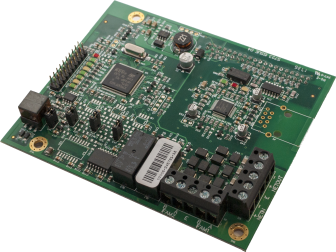
The Zone LED module contains 48 LEDs and is connected to the LCD Main Processor Board of the XT+ Extinguishant Control Panel. A maximum of three Zone LED modules can be connected to provide the fascia with 144 Zone LED indicators. The following figure illustrates the component-side of the Zone LED Module:
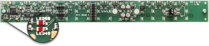
The component side of the Zone LED module is visible when the cabinet door is open. Zone LED indicators are not present on the component-side of the Zone LED module. The opposite side of the image shown contains Zone LED indicators.
| LED Number | Description |
|---|---|
| LED 49 | Flashes red to identify receiving data. |
| LED 50 | Flashes red to identify functional status of the Zone LED module. |
16 Channel I/O Interface Card (K1171)
The 16 Channel I/O Interface enhances the versatility of the alarm system by providing additional input and output capabilities to the XT+ Extinguishant Control Panel. Inputs and outputs can be selected for up to 16 individual channels. All inputs and outputs are configured in the same way as devices connected to addressable loops of the panel. The 16 Channel I/O Interface can be configured to contribute or act upon cause and effect logic.
Use Case Examples
The 16 Channel I/O Interface can be used to interface the XT+ panel to a NAC extender or Voice Evacuation system, by providing
- inputs to the XT+ panel for dry contact closures such as General Trouble, AC Power Trouble, or Battery Trouble from these devices.
- outputs from the panel to control various NAC or Voice Evacuation outputs.
The 16 Channel I/O Interface can be used to interface the XT+ panel to a secondary panel or releasing panel, by providing
- inputs to the XT+ panel for dry contact closures such as Fire, Supervisory, and Trouble from these panels, and various stages of release from the releasing panel.
- outputs from the panel to activate NAC outputs on these panels.
Restrictions
Inputs are intended for use as control signals from other life safety equipment. Inputs of this device are not supervised, and therefore cannot be used directly as initiating circuits for life safety applications within a UL listed system. Outputs are intended for use as control signals to other life safety equipment. Outputs of this device are not supervised, and cannot be directly connected to notification or releasing-type appliances in a UL listed system.
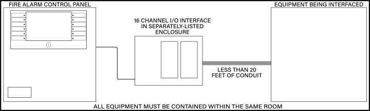
In a UL listed system, the 16 Channel I/O Interface:
- must be housed in a separately-listed enclosure.
- must be located in the same room as the XT+ panel.
- must be located in the same room as the equipment being interfaced.
- must be wired in conduit (or equivalently protected against mechanical injury) and within 20 feet of equipment being interfaced.
- must not be used to control the release of extinguishants.
For more information about the 16 Channel I/O Interface, refer to the 16 Channel I/O Interface Information Guide (MAN-1438).
XT+ Network Vision Annunciator (S787)
XT+ Network Vision Annunciator
TRC00NC-10 (Red), TRC00NC-40 (Gray), TRC00NC-60 (Black)
The XT+ Network Vision Annunciator is a display and control unit which duplicates the indications and primary controls of XT+ Extinguishant Control Panels connected to the same network. The Annunciator connects via the network interface, and any number of repeaters can be connected up to the maximum number of nodes allowed by the network.
XT+ Network Vision Annunciators can be configured to replicate fire control panel functionality or to operate as simple, display-only devices for applications where access to fire alarm controls are inappropriate. The Annunciator can be configured to display events from any combination of nodes on the network.
For more information about the XT+ Network Vision Annunciator, refer to the XT+ Network Vision Annunciator Information Guide (MAN-1434).
Media Gateway™ Panel Module (S788)
The Media Gateway™ is a communication panel module for the XT+ Extinguishant Control Panel. It provides connectivity to a remote monitoring center via Sur-Gard Fibro or dial-up. SIA is the recommended format for usage, but Contact ID is also supported. Transmission can be made through one or two telephone lines, and/or IP through Ethernet. Standard reporting codes have been pre-defined, although the user may customize these codes through the Loop Explorer 2 programming application.
For more information about the Media Gateway Panel Module, refer to the Media Gateway Panel Module Information Guide (MAN-1439).
8 Channel Relay Panel Module (S791)
The 8 Channel Relay Panel Modules have 8 voltage-free, unsupervised changeover relay contacts, each of which can be individually programmed.
All outputs are configurable in the same way as devices connected to the loops and all may be acted upon by cause and effect logic. These boards are typically used in applications which require more than the four standard relay outputs, such as signaling to other systems or plant control.
For more information about the 8 Channel Relay Panel Module, refer to the 8 Channel Relay Panel Module Information Guide (MAN-1440).
Batteries
Batteries are used as a secondary power source for the XT+ Extinguishant Control Panel, in the event that the primary power source (AC) fails.
Required standby battery capacity is dependent on the required standby period and load of the XT+ Extinguishant Control Panel system. Determine the current consumption of the fire alarm system for alarm and standby conditions. Use these maximum current values to determine the minimum required battery capacity of the fire alarm system.
Perform the installation only after calculations have been completed and a suitable battery capacity determined. Refer to Calculations or Loop Explorer 2 to determine the minimum required standby battery capacity of the system.
Standby Battery Type
The XT+ Extinguishant Control Panel is a 24 volt system designed to use Valve Regulated Lead Acid (VRLA) batteries as a secondary (backup) power source. VRLA batteries are not commonly available in 24V, so two 12V batteries are typically used, wired in series.