Appendix G: Specifications
This appendix provides electrical and environmental specifications for the XT+ Extinguishant Control Panel. Current levels provided in the tables of this appendix are maximum ratings unless otherwise indicated.
Operating Constraints
Installation of the XT+ Extinguishant Control Panel must include the operating constraints of the system to maintain continuous signal monitoring and reporting. Operating constraints are based on the current-driving capability of the panel while maintaining external loading caused by devices and cabling.
External loading must be selected within the limits of the XT+ Extinguishant Control Panel to provide continuous operation. External loading is caused by individual or multiple combinations of Signaling Line Circuits, Notification Appliance Circuits, and Initiating Devices. It is also caused by the size and length of cabling connections. Refer to Calculations to determine the appropriate size and length of cabling.
Electrical
AC Input Ratings
AC line and AC neutral terminals are supervised for open and short circuits, provided standby batteries are functional.
Power Supply
Fuses
|
Power Supply |
Description |
|---|---|
|
5.25 A |
AC Input, 3 A, 250 VAC, slow blow, 5 x 20 mm |
|
10.25 A |
AC Input, 5 A, 250 VAC, slow blow, 5 x 20 mm |
24 VDC Output Ratings
|
Designation |
Description |
|---|---|
|
Output voltage |
22V DC minimum, 26.4V DC maximum |
|
Ripple Voltage |
1 V Maximum |
|
Maximum Standby Current |
Rated maximum output current which can be supplied continuously in normal standby. |
|
|
1.9 A |
|
|
3.4 A |
| Maximum Alarm Current | Rated maximum output current which can be supplied in alarm. |
|
|
4 A |
|
|
8 A |
Standby Battery Ratings
Ground Trouble Indication
A ground trouble indication occurs on the XT+ Extinguishant Control Panel when 30K Ohms or less exists between the ground and either DC RTN or +24 VDC of the power supply.
System Power
When AC power is present, the system operates entirely from AC power (primary). During an AC power failure, the entire system load is transferred to the standby batteries (secondary).
Standby and Alarm Current
Standby and Alarm Currents of the XT+ Extinguishant Control Panel with two loops are provided below. Two loop operation includes System A Panel Module, System B Panel Module, and the Dual Loop Panel Module. Two loop operation represents the minimum board configuration of the XT+ Extinguishant Control Panel. The data excludes all external loads. Primary loads assume a fully charged battery.
5.25 A Power Supply
|
Standby Load (mA) |
Alarm Load (mA) |
Description |
|---|---|---|
|
244 mA @ 115 VAC |
272 mA @ 115 VAC |
Line current for standby and alarm when battery charge current is less than 30 mA. |
|
162 mA @ 230 VAC |
177 mA @ 230 VAC |
Line current for standby and alarm when battery charge current is less than 30 mA. |
|
560 mA @ 24 VDC |
650 mA @ 24 VDC |
Battery current for standby and alarm when AC power failure condition is present. |
10.25 A Power Supply
|
Standby (mA) |
Alarm (mA) |
Description |
|---|---|---|
|
220 mA @ 115 VAC |
234 mA @ 115 VAC |
Line current for standby and alarm when battery charge current is less than 30 mA. |
|
176 mA @ 230 VAC |
181 mA @ 230 VAC |
Line current for standby and alarm when battery charge current is less than 30 mA. |
|
550 mA @ 24 VDC |
620 mA @ 24 VDC |
Battery current for standby and alarm when AC power failure condition is present. |
The data provided above for standby and alarm current includes loads of a two loop fire control panel alone and excludes current loads from external devices or equipment.
Battery
Rechargeable Standby Battery Circuit
|
Designation |
Description |
|---|---|
|
Standby Battery Type |
Two 12 VDC, rechargeable, valve-regulated, lead-acid batteries wired in series |
| Charger Type | Temperature compensated, current limited float charger |
|
Low Battery Disconnect Voltage |
19 V (+/- 1 volt) |
|
Standby Battery Capacity |
Installation-dependent. Refer to Determining the Standby Battery Capacity to determine the amp hour rating of the standby batteries. |
|
Standby Battery Charge Voltage |
27.6 V nominal, temperature-compensated and current-limited |
|
Charge Current |
Maximum charging current of standby batteries. |
|
5.25 Amp Power Supply
|
1.25 A |
|
10.25 Amp Power Supply
|
2.25 A |
Standby Battery Loads
Standby battery loads are generated by measuring the series battery current of the power supply following a power failure condition. Standby and alarm current of the XT+ Extinguishant Control Panel can include all or part of the following loads:
Cabling
Specify cabling that meets or exceeds NFPA 72 and UL 864 guidelines.
Cable Maximum Parameters for Network
|
Property |
Ratings |
|---|---|
|
Resistance |
100 Ω total for both conductors |
|
Core to Core Capacitance |
300 nF |
|
Core to Screen Capacitance |
450 nF |
|
Inductance Per Core |
600 µH |
RS-485 Serial Data and Terminal Capacity
|
Property |
Description |
|---|---|
|
Serial Data Connection |
up to 3900 feet of 18/2 FPLR |
|
Maximum Terminal Capacity |
|
| Cable Maximum Parameters | 25 Ω per conductor, 600 µH per conductor, 300 nF |
SLC Loop Ratings
The following ratings represent Hochiki DCP Protocol SLC loops of the XT+ Extinguishant Control Panel.
|
Connection |
Rating |
|---|---|
|
LOOP ( - OUT ), ( + OUT ) |
36 V DC @ 400 mA |
|
LOOP ( - IN ), ( + IN ) |
36 V DC @ 400 mA |
Maximum Cable Capacitance: 1 µF
Maximum Wiring Voltage Loss: 6.4 V
Refer to SLC Loop Cabling for maximum allowable cable length calculations.
Main Back Board
NAC Outputs
| NAC Outputs |
Terminal |
|---|---|
| NAC 1 |
( + ), ( - ) |
| NAC 2 |
( + ), ( - ) |
| NAC 3 |
( + ), ( - ) |
| NAC 4 |
( + ), ( - ) |
NAC 1 and 2 can be configured to provide one Class A circuit (NAC 1&NAC 2) or two Class B circuits (NAC 1 and NAC 2).
NAC 3 and 4 can be configured to provide one Class A circuit (NAC 3&NAC 4) or two Class B circuits (NAC 3 and NAC 4).
Each NAC circuit, whether Class A or Class B, has the following ratings:
| AUX Power Output Range | Channels configured to power non-NAC devices are rated special application 20V - 26.4V at 2A max, power-limited. Refer to NAC Power Output Modes for compatible devices. |
| Quiescent Current Consumption | 30 mA |
| Maximum Current Consumption | 50 mA (exclude current draw on outputs) |
| Current per NAC Output | 2.5 A per channel, power-limited |
| Fuse (Electronic) |
Average Current Limit: 1 to 2.5 A, programmable |
| Supervision | Reverse-polarity |
| End-of-Line Device | Diode |
| Short Circuit Threshold | 130 Ohms +/- 20% |
| Maximum Line Impedance | 4V loss (load-dependent) |
Regulated NAC Outputs
NAC outputs operate in a regulated mode when conforming to specific levels of continuous or pulsed DC. NAC outputs meet requirements for regulated levels when the output current does not exceed the constraints described below.
| Regulated Non-Pulsing Output Current |
Currents cannot exceed 2.5A from any single NAC output: Combined currents of all four NAC outputs cannot exceed 5A System must not exceed maximum power supply output rating. |
| Regulated Pulsing Output Current |
5.25A Power Supply - Regulated pulsing DC output = Max 500mA total across all NACs 10.25A Power Supply - Regulated pulsing DC output = Max 600mA from any NAC output, Max 2.4 A per Board System must not exceed maximum power supply output rating. |
Refer to Specifications for operating NAC outputs in the regulated mode.
Special Application NAC Outputs
NAC outputs can operate in a special application mode. NACs configured for special application have specific loading limitations, as detailed below.
| Manufacturer | Maximum No. of Devices per Channel | Maximum Current Draw per Channel | Power Supply |
Maximum Current Draw Across All NACs1 |
|---|---|---|---|---|
| Amseco | 27 | 2.4A |
|
2.5A |
|
|
5A | |||
| Gentex | 32 | 2.5A |
|
2.5A |
|
|
5A | |||
| System Sensor | 20 | 1.32A |
|
2.1A |
|
|
5A | |||
| Wheelock | 41 | 2.5A |
|
2.5A |
|
|
5A |
1 When System Sensor is used in combination with any other manufacturer, the 2.1A limit applies across all NACs.
Refer to Specifications for operating NAC outputs in the special application mode.
AUX 24V
|
Terminal |
Rating |
|---|---|
| AUX 24V (1) OUT ( + ) and ( - ) |
Regulated 24 VDC @ 900 mA |
| AUX 24V (1) RTN ( + ) and ( - ) |
Supervision only. Not an output. |
| AUX 24V (2) OUT ( + ) and ( - ) |
Regulated 24 VDC @ 900 mA |
| AUX 24V (2) RTN ( + ) and ( - ) |
Supervision only. Not an output. |
Relay Ratings
|
Terminals |
Connection |
Ratings |
|---|---|---|
|
(NO), (C), and (NC) |
|
|
|
(NO), (C), and (NC) |
|
Network (RS-485)
|
Terminal |
Rating |
|---|---|
|
W |
Ground for cable shield (if applicable) |
|
( + ), ( - ) IN |
Data 3.3 V, current-limited |
|
( + ), ( - ) OUT |
Data 3.3 V, current-limited |
RS-485 I/O
|
Terminal |
Rating |
|---|---|
|
W |
Ground for cable shield (if applicable) |
|
( + ), ( - ) IN |
Reserved for future use. |
|
( + ), ( - ) OUT |
Data 3.3 V, current-limited |
The RS-485 I/O utilizes standard RS-485 signaling in multi-drop mode with 120 Ohm terminations.
Fire Routing Output 1
Reserved for future use.
Prog Inputs
|
Terminals |
Rating |
|---|---|
|
1, 2, 3 |
Supervision: None |
Fire Routing Input
Supervised input to receive confirmation signal from fire routing equipment. Reprogrammable for any input event type.
|
Terminals |
Rating |
|---|---|
|
( + ), ( - ) |
Supervision: Class B |
Fire Routing Output 2
Reprogrammable for any output event type.
|
Terminals |
Rating |
|---|---|
|
( + ), ( - ) |
Regulated 24V DC @ 60 mA |
Prog Routing Input 1
Programmable for any input event type.
|
Terminals |
Rating |
|---|---|
|
( + ), ( - ) |
Supervision: Class B |
Prog Routing Output
|
Terminals |
Rating |
|---|---|
|
( + ), ( - ) |
24V max. |
Prog Routing Input 2
Programmable for any input event type.
|
Terminals |
Rating |
|---|---|
|
( + ), ( - ) |
Supervision: Class B |
Trouble Routing Output
Reprogrammable for any output event type.
|
Terminals |
Rating |
|---|---|
|
( + ), ( - ) |
Regulated 24V DC @ 60 mA |
Trouble Routing Input
Reprogrammable for any input event type.
|
Terminals |
Rating |
|---|---|
|
( + ), ( - ) |
Supervision: Class B |
System Information
|
Property |
Description |
|---|---|
|
Software Zones |
2000 zone capacity |
|
Software Groups |
5000 group capacity |
|
10,000 event capacity, 1 second resolution. Filterable and printable. |
|
| Cause and Effects | 5000 |
Mechanical
Fascia Components
|
Property |
Description |
|---|---|
|
Display |
Full color 800 x 480 LCD with resistive touch screen and automatic backlight dimming |
|
XT+ Printer |
40 column, front loading thermal (optional) |
|
Zone LED Indicators |
Up to 3 banks of 48 (144) (optional) |
Operating Environment
Dry indoor use only.
|
Temperature Range |
23°F (-5°C) - 120°F (49°C) |
|
Relative Humidity |
Up to 95%, non-condensing |
Cabinet Housing
| Housing | Description |
|---|---|
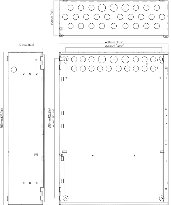
| Dimensions |
4 Slot Standard Cabinet - 420mm (W) x 590mm (H) x 153mm (D), approximately 16.5in (W) x 23.2in (H) x 6in (D) |
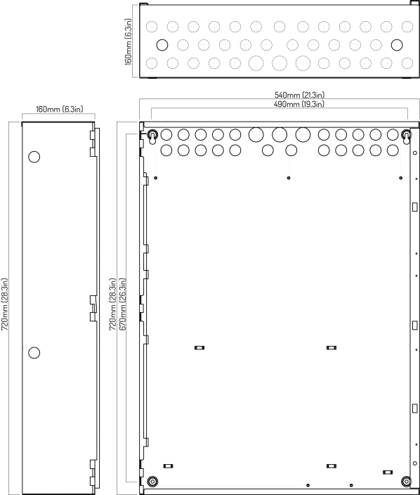
| 8 Slot Standard Cabinet - 540mm (W) x 720mm (H) x 160mm (D), approximately 21.3in (W) x 28.3in (H) x 6.3in (D) | |
|
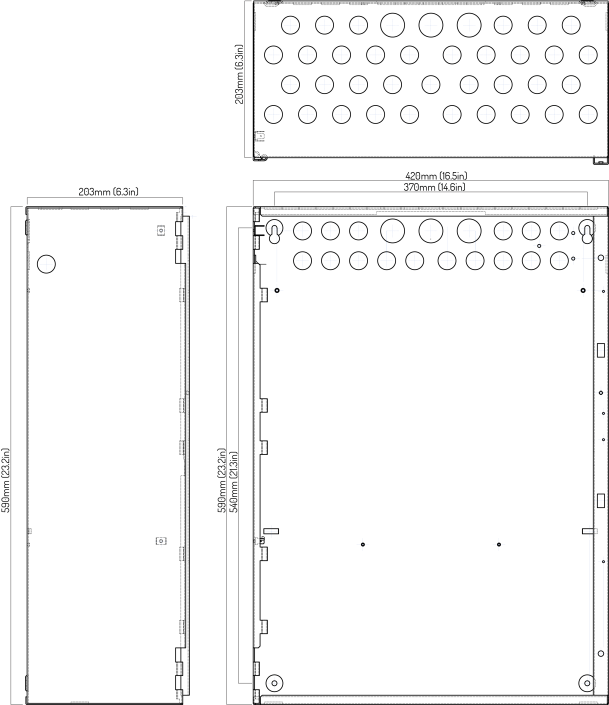
4 Slot Deep Cabinet - 420mm (W) x 590mm (H) x 203mm (D), approximately 16.5in (W) x 23.2in (H) x 8in (D) |
|
| 8 Slot Deep Cabinet - 540mm (W) x 720mm (H) x 212mm (D), approximately 21.3in (W) x 28.3in (H) x 8.3in (D) | |
| Construction
|
Standard and Deep Cabinet Models |
|
These models include:
|
|
| Finish | Epoxy powder coated |
| Color | Lid & Box - Red or Gray |
| Control Plate - RAL7016 | |
|
Cable Entry |
Standard and Deep Cabinet Models - 28 knockouts top, 19 knockouts back, 1 knockout each side |
| Mounting | Minimum size #12, Maximum size #14. 40mm (1.5in.) length |
This following figures illustrate the XT+ Extinguishant Control Panel cabinet housing options. All cabinets can be ordered with an optional second aperture to accommodate a printer or Fire In Zone LED indicators.
4 Slot Standard Enclosure
8 Slot Standard Enclosure
4 Slot Deep Enclosure
8 Slot Deep Enclosure