Installation
This section provides instructions for connecting cables, mounting, and testing the XT+ Extinguishant Control Panel for installation. The following is a general checklist for the installation of the panel. Detailed instructions are provided for each step.
WARNING! Disconnect AC and battery power before making any field connections. Double-check all termination points before applying power to the panel! Incorrectly terminated wiring may cause permanent damage to the panel.
IMPORTANT! The XT+ Extinguishant Control Panel installation must be performed by qualified service personnel. Maintain extreme care when anchoring the cabinet to the premises wall. Electronic components within the panel are vulnerable to physical damage from severe shock and vibration. Remove the cabinet door and fascia for the installation of the panel. Detailed instructions are provided for each step.
Preparing for Installation
- Refer to the checklist provided above before beginning the installation process. For detailed information, refer to the appropriate, referenced section in this document.
- Select a suitable operation environment. The site should be clean, dry, and not subject to shock or vibration. Ensure that the environment is free from wire ends, knockout tabs, and other debris.
- Familiarize yourself with the panel and components.
- The following items are not included with the XT+ Extinguishant Control Panel, but may be required for the installation:
- Two 12 VDC VRLA (Valve-Regulated Lead Acid) Standby Batteries - Required
- Mounting Hardware - Mounting hardware that secures the panel to the wall is not provided. Screws should be either a #10 or #12.
- A Ground Strap is required for handling circuit boards.
Mounting the XT+ Extinguishant Control Panel
IMPORTANT! Electronic components within the panel are vulnerable to damage from electrostatic discharge. Ground straps must be worn by installers before handling circuit boards to prevent damage from electrostatic discharge.
Mount the cabinet box on a flat, dry surface and align it so that it is at eye-level with the center of the panel GUI. Use the cabinet box as a template and mark the position of the mounting holes while ensuring that the wall is flat at the chosen location.
The XT+ Extinguishant Control Panel must be mounted in an accessible location. It must not be mounted in another enclosure or near sources of excessive heat. The XT+ Extinguishant Control Panel is intended for indoor, dry use only.
Use knockout tabs of the cabinet box to route external cabling into the panel.
IMPORTANT! Drilling additional holes in the cabinet will void the product warranty.
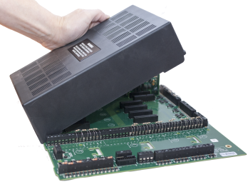
Removing Cabinet Components
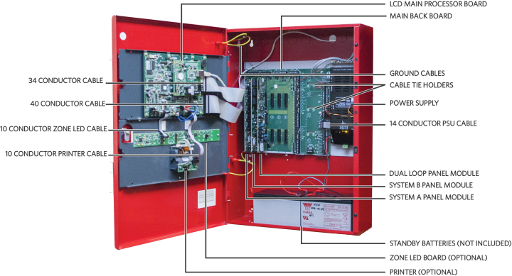
Remove the fascia, lid, backplate, and batteries before mounting the cabinet box. The fascia contains the LCD Main Processor Board and, optionally, Zone LED indicators and a printer. The backplate contains the Main Back Board, power supply, and grounding terminals. To remove these components:
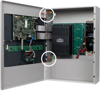
- Disconnect the four ground jumper cables from the cabinet.
- Disconnect the ribbon cables from the LCD Main Processor Board, leaving the cable ends connected to the Main Back Board.
- Remove the hinge pins of the fascia and then remove it from the cabinet box. Return the hinge pins to the hinges of the cabinet box for safekeeping.

- Remove the hinge pins of the cabinet lid and then remove the cabinet lid from the cabinet box of the fire control panel. Return the two hinge pins to the hinges of the cabinet box for safekeeping.
- Remove the retaining screws from the backplate, slide the backplate tabs up, and remove the backplate from the cabinet. The empty cabinet box is now prepared for mounting on the premises wall.
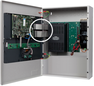
- If the power supply is not mounted to the backplate (as with an extension board), disconnect the power supply and remove it from the cabinet.
- Mark hole locations on the wall for mounting the empty cabinet.
- Drill four holes in the premises wall.
- Anchor the empty cabinet box to the wall using appropriate mounting hardware to secure it.
- Remove the necessary number of knockout tabs from the cabinet box and feed external cabling into the XT+ Extinguishant Control Panel.
Replacing Cabinet Components
- Replace the backplate and power supply.
- Replace the door and fascia.
- Reconnect the cabling.
Connecting and Dressing Cabling
This section describes connections between the power supply and the Main Back Board of the XT+ Extinguishant Control Panel. Separate high and low voltage wiring in the enclosure with a minimum gap of 0.25".
Connecting 24V and 14 Conductor Wiring
Refer to Connecting Field Wiring for specific details about proper wiring. To connect 24V wiring of the power supply to the Main Back Board:
- Connect the red wire from the positive ( + ) 24V terminal of the power supply to the positive ( + ) terminal on the Main Back Board.
- Connect the black wire from the negative ( - ) RTN terminal of the power supply to the negative ( - ) terminal on the Main Back Board.
- Connect the 14 Conductor Cable from the power supply to the Main Back Board.
Installing Power Supplies
XT+ Extinguishant Control Panels can be equipped with either a 5.25 Amp or 10.25 Amp power supply. Set DIP switches on the 5.25 Amp and 10.25 Amp Power Supplies before completing the installation process. Refer to DIP Switch Settings. The power supply settings must be performed to establish the optimal charge current of the standby batteries. These power supplies can be set to operate at
The 5.25 Amp Power Supply
The 5.25 Amp Power Supply contains a jumper setting for changing from 115 VAC to 230 VAC. Check the jumper setting prior to wiring and operating the 5.25 Amp Power Supply with the XT+ Extinguishant Control Panel.
Confirm that the 5.25 Amp Power Supply is set for 230 VAC before operating at 230 VAC. Permanent damage of the power supply will result if the 115 VAC jumper setting exists while operating the power supply at 230 VAC.
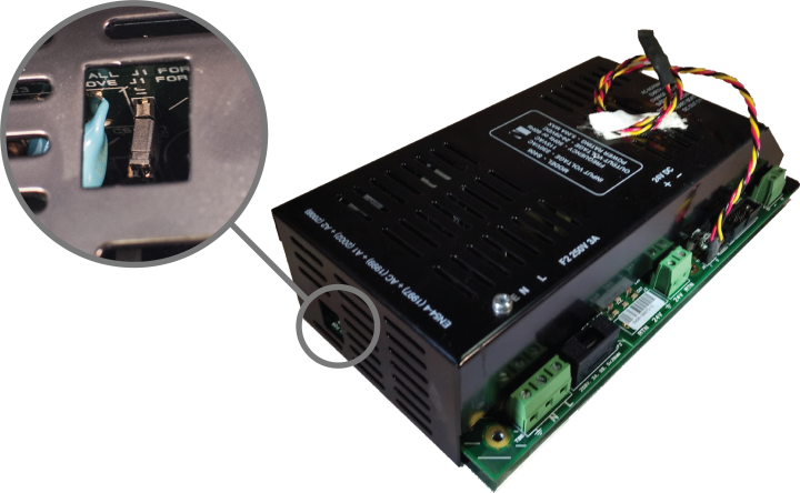
WARNING! Remove jumper J1 before operating the XT+ Extinguishant Control Panel at 230 VAC. Failure to remove jumper J1 prior to operating at 230 VAC will cause permanent damage to the 5.25 Amp power supply.
High voltage present on jumper pins. Remove AC power before changing jumper setting.
| Voltage | Jumper Required |
|---|---|
| 115 | Yes |
| 230 | No |
Refer to Connecting Field Wiring for specific details about wiring the power supplies. Provide an AC power connection to the terminal block from a 15 Amp branch circuit. The following figure illustrates AC connections of the 5.25 Amp Power Supply:
- Connect a wire from the ground terminal (
 ) to the grounding block of the cabinet box.
 - Connect a wire from the grounding block of the cabinet box to a ground. Provide this connection in close proximity to the cabinet box.
- Connect a wire from the neutral terminal (N) to the neutral of the power source.
- Connect a wire from the line terminal (L) to the line of the power source.
The 10.25 Amp Power Supply
Unlike the 5.25 Amp Power Supply, the 10.25 Amp Power Supply does not require a jumper to switch between 115 VAC and 230 VAC. The 10.25 Amp Power Supply provides an auto-detect feature that automatically compensates for input voltages of 115 VAC or 230 VAC.
Provide an AC power connection to the terminal block from a 15 Amp branch circuit. To connect AC power to the 10.25 Amp Power Supply:
- Connect a wire from the ground terminal () to the grounding block of the cabinet box.
- Connect a wire from the grounding block of the cabinet box to a ground. Provide this connection in close proximity to the cabinet box.
- Connect a wire from the neutral-terminal (N) to the neutral of the power source.
- Connect a wire from the line-terminal (L) to the line of the power source.
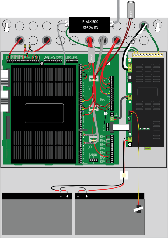
Connecting Standby Batteries
The XT+ Extinguishant Control Panel provides connections for two standby batteries. Refer to Calculations for determining the minimum required battery capacity for your fire alarm system. If your required battery capacity exceeds the space available in the cabinet, an appropriately-sized auxiliary UL listed battery cabinet suitable for fire alarm service will be required. If needed, install that cabinet (wired close-nippled) adjacent to the panel to minimize battery lead length.
WARNING! Battery terminals and leads are not power-limited. Shorts can cause a fire or an explosion. Use extreme caution while connecting standby batteries.
Refer to Connecting Field Wiring for specific details about connecting the standby batteries.
- Place two 12 VDC, VRLA, rechargeable, standby batteries in the base of the cabinet.
- Orient terminals of the standby batteries so that the positive ( + ) terminal of one standby battery is facing the negative ( - ) terminal of the other.
- Connect the black wire of the power supply to the negative ( - ) terminal of Battery 1.
- Connect the red wire of the power supply to the positive ( + ) terminal of Battery 2.
- Connect the jumper wire from the ( + ) of Battery 1 to the ( - ) of Battery 2.
- Route battery leads at least 0.25" from all other cabling.
The series connection described provides the 24 V standby voltage required by the panel. Do not connect the two batteries in parallel. A parallel connection will not provide the 24 V required for operating the panel in a standby condition.
The battery connections can be made while AC power on or off. If AC power is off, the battery connection will not be recognized (and the unit will remain unpowered) until AC is restored. Once AC power is on and the batteries are connected, examine the LED Status Indicators on the power supply:
- Confirm that the AC NORMAL and DC OUT ON indicators are both illuminated, and the HEARTBEAT indicator is blinking yellow.
- Confirm that BATTERY DISCON is off. If it is on, recheck the battery connections and test or replace the batteries.
- Wait 3 minutes and confirm that no trouble indicators are illuminated.
Using a volt meter, measure the voltage across each battery separately. Typically, the voltage of each battery will measure 12.0 to 14.5 volts depending on the level of charge. Voltages below 12.0 are possible if the battery is severely discharged. Compare the two battery voltages. A difference of more than 1 volt may indicate a problem with the batteries.
Installing Optional Panel Modules
Panel modules are installed at the factory according to customer requirements. In some situations, it may be necessary to install additional panel modules to satisfy site configuration requirements. This section describes procedures for installing and configuring panel modules. Before installing optional panel modules, check and set the DIP switch settings, if applicable.
DIP Switch Settings
Each panel module of the XT+ Extinguishant Control Panel must contain a unique setting before being connected to the Main Back Board. The binary setting of the DIP switch sets the specific address for the panel module. The numeric order of the address setting between modules does not impact operation, but each panel module must be assigned a separate / unique address.
The black portion of the DIP switch identifies the switch actuator.
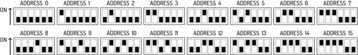
Address 0 is shown above for illustrative purposes only. Address 0 should never be used.
For addresses above 15, switches 5 and 6 will need to be used.
- For address 16-31, switch 5 should be in the ON position. Switch 5 ALONE adds 16 to the address number. For example, for address 20, set the switch position to address 4 shown above and switch 5 in the ON position.
- For address 32-47, switch 6 should be in the ON position. Switch 6 ALONE adds 32 to the address number.
- For address 48-63, switches 5 AND 6 should be in the ON position. Switches 5 and 6 TOGETHER adds 48 to the address number.
Placement
To install modules on the XT+ Extinguishant Control Panel:
- Disconnect AC power and standby batteries prior to performing the module installation.
- Remove the retaining screw and plastic cover.
- Remove the panel module from the protective packaging using adequate electrostatic protection.
- Point the conductor side of the panel module toward the backplate.
- Insert the notched end of the panel module in the metal guide notch of the backplate at an angle, as shown.
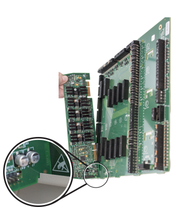
The photo above is an example of panel module placement and may not be representative of the specific module and slot placement described in this guide. Refer to the checklist above for details on placement.
- Rotate the panel module until all conductors are securely inserted into connectors of the Main Back Board.
- Replace the cover onto the Main Back Board.
- Reconnect the batteries and restore AC power.
Installing the Network Module
The Network Module provides enhanced high-speed communication for networking up to 127 fire control panels, (addressed from 1-127). To install the network module of the XT+ Extinguishant Control Panel:
- Switch off AC power and disconnect the battery .
- Connect the 40 conductor connector of the Network Module to the 40 conductor connector of the LCD Main Processor Board as shown.
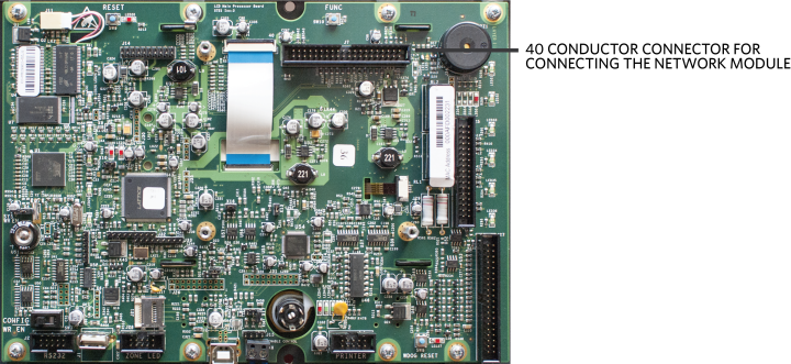
- Secure the Network Module to the LCD Main Processor Board with supplied hardware .
- Reconnect the battery and restore AC power.
Network Connections
Provide network connections to NETWORK IN and NETWORK OUT terminals of the XT+ Extinguishant Control Panel's Main Back Board after installing the Network Module. The following figure illustrates the typical network connections of a 3 panel, Class X network:
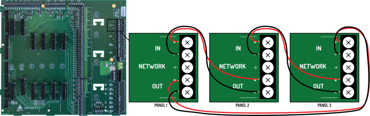
Because network connections are supervised, if a network module is installed and there are no other devices on the network, the IN and OUT network terminals must be connected together to prevent an OPEN CIRCUIT TROUBLE indication.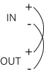
Bridge networking is supported for FireNET and FireNET Plus panels. Advanced features are not available when using bridge networking.
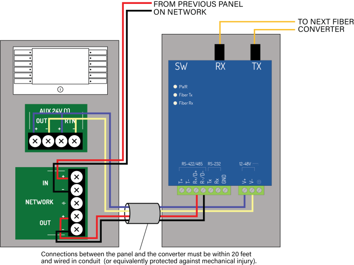
Fiber Optic Networking
When designing or installing a network of panels, any network segment or combination of segments can be connected with fiber optic cable instead of copper wire. Two fiber optic converters are required per segment as shown. Connections between the panel and the converter must be within 20 feet and wired in conduit (or equivalently protected against mechanical injury). Converter DIP Switch settings must be set as shown . Refer to the Equipment List for the model numbers of the fiber converters.
| Single-Mode | Multi-Mode | |
|---|---|---|
| Fiber Types | 9/125 μm, 8.3/125 μm, 7/125 μm, or 10/125 μm | 50/125 μm, 62.5/125 μm, or 100/140 μm |
| Wiring Distance | 24.8 miles (40 km) | 3.1 miles (5 km) |
| Serial Connection RS-485-2W |
Built-in 120 Ohm Terminator Enable |
Fiber Mode Point-to-Point Mode |
|
| SW1 | SW2 | SW3 | SW4 |
| OFF | ON | ON | OFF |
Connecting Field Wiring
Power-limited conductors must be installed using Types FPL, FPLR, FPLP, or equivalent cables. When connecting field wiring, separate high and low voltage wiring in the enclosure with a minimum gap of 0.25".
WARNING! Disconnect AC and battery power before making any field connections.
WARNING! Do not route low-voltage cabling through the same conduit as AC lines. AC power lines should be threaded through a dedicated conduit. Refer to the following illustration when connecting any wiring.
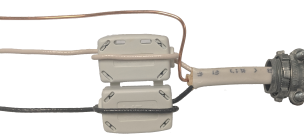
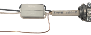
Ferrite Installation
To reduce the impact of electromagnetic interference (EMI), the ferrite provided with the XT+ Extinguishant Control Panel must be installed onto the incoming AC wiring. These photos illustrate how the ferrite should be installed.

Internal View |
External View |
Closed View |
|
Live and Neutral wire cores must be doubled around the ferrite. When the cores are in place, close the ferrite with a ‘click' sound.
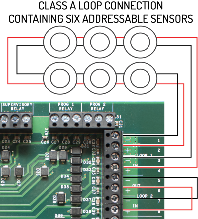
Class A SLC Loops
The XT+ Extinguishant Control Panel provides a trouble signal when unused loops are not terminated. All loops are supervised. Follow NFPA guidelines for placement of isolators with Class A wiring. |
|
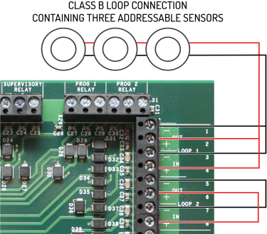
Class B SLC Loops
|
Class B loops may not be permitted in all regions. Check local codes of practice before using Class B SLC circuit configurations.
SLC cabling must be sized according to length and device load to ensure that the voltage-drop of the cable does not result in an inadequate operating voltage on the circuit. Refer to the XT+ Extinguishant Control Panel Information Guide (MAN-1252KE) for an example of how isolators may be used on a Class B circuit. |
|
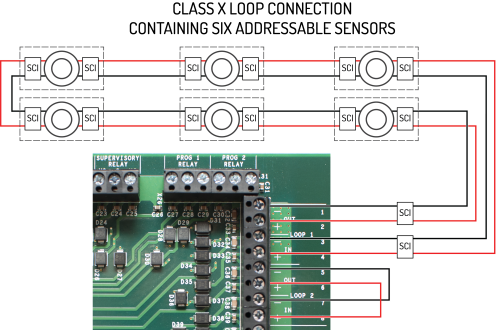
Class X SLC Loops
|
|
|
The XT+ Extinguishant Control Panel provides a trouble signal when unused loops are not terminated. All loops are supervised. Follow NFPA guidelines for placement of isolators with Class X wiring. When using Class X wiring, SCI Short Circuit Isolators must be installed before and after each analog addressable device on the SLC loop. Alternatively, analog devices with built-in SCI may be used. The wiring from the control panel to the first SCI and from the last SCI back to the control panel must be in conduit. |
|
Notification Appliances
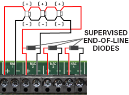
Notification appliance circuits can be configured in pairs for Class A operation. Class A operation can be assigned to the first pair of notification appliance circuits (NAC1&2) or the second pair (NAC3&4) or both pairs.
When wiring a pair of NACs for Class A operation, only one of the two End-of-Line diodes is used. Remove the one from the +/- terminals of the first NAC. Leave the other in-place on the terminals of the second NAC.
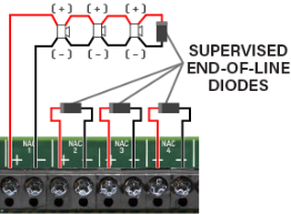
For Class B operation, the End-of-Line diode must be removed from the NAC terminals and connected across the terminals of the last device on the NAC circuit.
Branching of Class A or Class B notification appliance circuits prevents proper circuit supervision and is not permitted.
Connecting Notification Appliances
|
|
| Connection of notification appliances in a Class A configuration. | Connection of notification appliances in a Class B configuration. |
Do not insert more than one conductor per terminal. Use wire nuts or other suitable splice connectors to connect the end-of-line diode and Class A loop return wire. Cable gauge must be sized according to length and device load to ensure that voltage-drop of the cable does not result in less than the minimum operating voltage of the notification appliances. Different limitations will apply for devices with a higher or lower minimum working voltage. Refer to Specifications for cabling information.
To install notification appliances on the XT+ Extinguishant Control Panel:
- Connect notification appliances and End-Of-Line diodes to the NAC output.
- Connect End-Of-Line diodes to unused NAC outputs.
- Maintain the limit for maximum wire length of the circuit.
Notification appliances connected to NAC outputs on a single panel are synchronized. Notification appliances connected to SLC loops on a single panel are synchronized. However, notification appliances on separate panels are not synchronized. Per NFPA 72,
|
Audible Devices |
The installation of one group of synchronized-audible notification appliances shall not be installed in hearing range of another group of synchronized-audible NACs. |
|
Visual Devices |
The installation of one group of synchronized-visual notification appliances shall not be installed in line-of-sight of another group of synchronized-visual notification appliances. |
Refer to Equipment List for synchronization devices that are UL listed and authorized for use with the XT+ Extinguishant Control Panel. Refer to Calculations to determine wire size requirements for your application.
Connections for NAC Power Output Modes
There are 3 NAC power output modes: continuous constant power, door holder, and resettable. NAC power outputs can be wired as 2-wire or 4-wire circuits as shown. When wired using 2-wire configuration, select "Class B" in the configuration menu. When wired using 4-wire configuration, select "Class A" in the configuration menu.
|
When using a NAC in a power output mode, each device requires a blocking diode (not provided) to be connected in series. These diodes can be any of the following:
|
Regardless of the wiring schema,
When the NAC is used in continuous constant power mode, it is a special application output with a voltage range of 20.0 - 26.4V.
When configuring for door holder, the circuit is a regulated 24V output and meets the requirements for a Class D circuit.
When the NAC is used in resettable mode, it is a special application output with a voltage range of 20.0 - 26.4V. It can be used to power the following:
- System Sensor i3 series Models: 4W-B, 4WT-B, 4WTA-B, 4WTR-B, 4WTAR-B, 4WITAR-B
- System Sensor i4 Series Models: COSMO-4W, COSMOD4W
- System Sensor End-of-Line Relay: EOLR-1
When powering these devices, the circuit acts as a Class B pathway only when an EOLR-1 is the last device on the circuit and the relay contacts are supervised. The wiring loss must not exceed 8V. Refer to the System Sensor Installation Instructions for wiring information.
AUX 24V 1 and AUX 24V 2
The AUX 24V output terminals provide regulated, non-programmable 24V DC for powering ancillary devices such as loop modules, I/O boards, and remote displays. The outputs are fused at 900 mA and include a maximum load rating of 900 mA. Outputs of AUX 24V 1 and AUX 24V 2 are also supervised for circuit trouble conditions.
Wiring gauge on AUX 24V 1 or AUX 24V 2 outputs must be sized as a function of cable length and device load to ensure that voltage-drop of the cable does not result in less than the minimum operating voltage at the ancillary devices.
|
Connect the ancillary devices to the OUT terminals. The OUT terminals supply 24V power and provide short circuit monitoring. Connect RTN terminals to the last ancillary device. The RTN terminals provide open circuit monitoring. If open circuit monitoring is not required, the RTN terminals must be connected to the OUT terminals to prevent reporting of OPEN CIRCUIT TROUBLE. |
This illustrates a Class B circuit that provides open circuit monitoring. |
Relay Contacts
The XT+ Extinguishant Control Panel contains five programmable relays that provide volt-free changeover. These relays include:
|
Activates on any trouble and clears when all troubles are clear. |
|
| Activates on any fire condition and remains active until all fire conditions are clear. | |
| Activates on any supervisory condition and remains active until all supervisory conditions are clear. | |
|
PROG 1 RELAY |
User-definable. Not programmed by default. |
| PROG 2 RELAY | User-definable. Not programmed by default. |
Each relay has three volt-free changeover contacts labeled NO, COM, and NC respectively.
Dry contacts between the NO terminal and the COM terminal are open when the output is inactive, and closed when the output is active.
Dry contacts between the NC terminal and the COM terminal are closed when the output is inactive, and open when the output is active.
Each relay can be configured independently through Loop Explorer 2 or the panel GUI using Access Level 3. Refer to the Programming the Panel for LE2 information. Refer to Specifications for operating characteristics of these field terminals.
Network
These terminals provide Class X connections for intra-panel and annunciator networking and allow for individual panels to communicate the following data with each other:
- Trouble, Supervisory signals
- Alarms: CO, Fire
- Other events tab information
Data passed can be reported at each panel GUI and trigger panel responses such as the buzzer or fire alarms. Networked panels that go off-line will appear as missing at networked panels. Refer to Network Connections for wiring information.
RS-485 I/O
These terminals provide data communication between the panel and legacy products, such as the 16 Channel I/O Interface Card. Connections are:
Fire Routing Output 1
Reserved for future use.
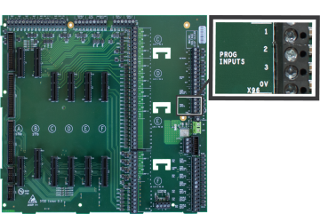
Prog Input
There are three programmable Inputs (PROG INPUT) and one 0V terminal. The inputs are non-supervised and are designed to be activated by voltage-free contacts. To activate, connect a PROG INPUT to the 0V terminal. Do not insert more than one conductor per terminal. There are additional 0V terminals if needed.
The default configuration of all three programmable inputs is non-latching, transparent. They must be configured to perform a function. The line impedance of the circuit connection to the Prog Input terminals must be less than 50 ohms. Each programmable input can be separately configured to provide actions, delays, zones, and location messaging using the panel GUI.
|
|
|||||||||||||||
|
For wiring Programmable Inputs:
|
||||||||||||||||
Routing I/O Terminals
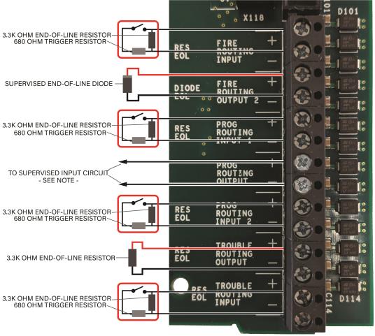
NOTE The output impedance of the Prog Routing Output is 3.3k ohms when in the NORMAL state and 680 ohms when in the ACTIVATED state. Connect these terminals to any device input that matches these impedance values.
Installing Addressable Devices
This section describes installation requirements and constraints for addressable devices on the XT+ Extinguishant Control Panel. The addressable devices described in this section include SLC Devices.
SLC Detector Spacing
Install SLC detectors with spacing as specified in NFPA 72.
SLC Device Detector Sensitivity
SLC device sensitivity is configurable using the panel GUI or LE2. Refer to the Programming the Panel for LE2 information. Sensitivity levels should be determined and planned in advance.
Detector Calibration / Drift Compensation
Detector calibration automatically occurs once per day. The XT+ Extinguishant Control Panel is responsible for drift compensation of individual smoke sensors. It will make automatic sensitivity checks and sensor adjustments once per day.
Addressing an SLC Module
Hochiki Protocol
All SLC modules must have a unique address number that acts as a point of reference for the panel. An SLC module address number can be any number from 1-127. SLC detectors that are paired with compatible SLC sounder bases provide the sounder base with a unique ID of detector address +127.
Addressing an SLC module requires the use of an Analog Device Programmer (not included with the XT+ Extinguishant Control Panel). Use the operating instructions when programming each device.
It is not necessary to address sounder bases.
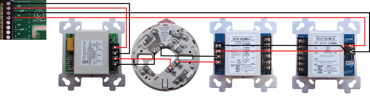
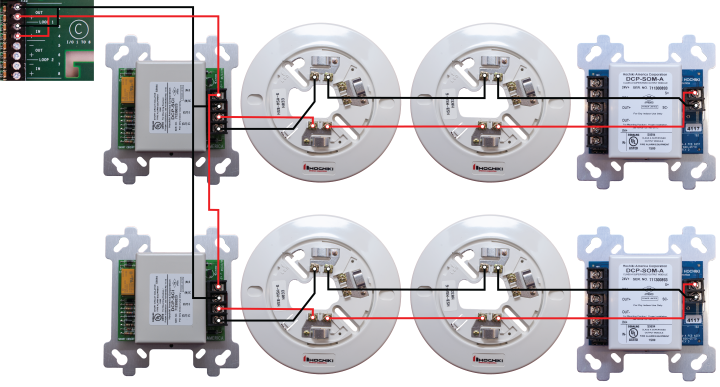
Connecting SLC Devices
Hochiki Protocol
Each SLC device must be connected using S and SC terminals; S to S and SC to SC. Refer to device-specific wiring requirements when connecting each device.
Devices with IN and OUT S and SC terminals should be connected IN to OUT and vice versa.
SC on the device should connect to LOOP (-) on the panel. S on the device should connect to LOOP (+) on the panel.
|
| Class A SLC Wiring Example - Hochiki Protocol |
|
|
|
| Class B SLC Wiring Example - Hochiki Protocol
SCIs should be located at or near the panel. |
Installing Municipal Boxes
The figure below illustrates typical municipal box connections of the XT+ Extinguishant Control Panel:
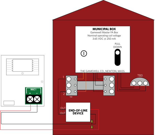
Perform this installation to connect the Gamewell Master F. A. Box for municipal-station notification. Install this product in accordance with NFPA 72, NEC 70, the National Electrical Code and all local codes. The NAC output can provide a non-pulsing, regulated 24 VDC, 2.5A maximum output when a fire condition is reported to the XT+ Panel. The OUT leads of the EOLD (K14070) shall connect directly to the terminal block of the municipal box.
Testing the Installation
Once all field wiring connections are complete, test the power supply, field circuits, and panel GUI to ensure proper operation of the XT+ Extinguishant Control Panel.
Panel Start-up
- Connect the batteries and apply AC power to the XT+ Extinguishant Control Panel.
- Allow the panel to go through its start-up process.
- Black screen with Bootloader version displayed. (<1 min.)
- Blank screen. (< 1 min.)
- Animated loading circle with brief Lamp Test. (< 1 min.)
- Splash-screen with Loading Graphics. (< 1 min.)
- After Loading Graphics clears, press Controls & Other Events> Other Events to display details of ongoing start-up processes. Other Events will always include initialization of the SLC loops, but may include additional items as well, such as User Logged In and Bootloader Update events.
At this stage, it is common for many trouble events to be reported. The most common is "Unexpected Device". This is a normal part of panel commissioning.
The start-up process is complete when all of the panel's Other Events clear.
- If Bootloader Update events were present during the start-up process in step 2, power down the panel and repeat Panel Start-up.
Do not power-down the panel during a Bootloader Update.
• User Logged In indicates that a key switch is turned to the Enable position or a user access code has been entered.
• Bootloader Update indicates software on panel modules is being updated by the main panel. This typically occurs
only when a panel module is changed or the main panel firmware is updated.
• If the panel is part of a network, some status events may reflect the status of other network nodes.
Loading Configuration
- Load (or import) the appropriate configuration from Loop Explorer 2. After the import, the panel will begin device initialization.
The node address must be set on the panel before importing a configuration from LE2.
- Press Controls & Other Events > Other Events to display details of the ongoing device initialization process.
- Once initialization is complete, address any outstanding troubles that may be reported.
- Confirm that the Fire System Normal condition is displayed.
Testing the Power Supply
Perform the following tests to confirm operation of the power supply:
- Apply AC and battery power to the XT+ Extinguishant Control Panel.
- Check that the AC Normal LED is illuminated on the power supply.
- Check that the Heartbeat LED is flashing on the power supply.
- Remove AC power and ensure that the standby batteries are powering the fire control panel. The AC Normal LED on the power supply switches off after 30 seconds to indicate the loss of power.
- Reapply AC power to the XT+ Extinguishant Control Panel.
- Disconnect the red wire from the Standby Battery terminal. The Battery Disconnect LED on the Power Supply illuminates and the fire control panel continues to operate.
- Reconnect the red wire from the Standby Battery terminal.
Check connections and test voltages at the primary and secondary of the power supply if the panel does not operate as described above.
Testing the Field Circuits
Perform the following field circuit tests to confirm proper connections of the loops, NACs, inputs, and outputs:
- Connect external devices to field terminal loops, NACs, inputs, and outputs.
- Confirm that correct connections exist between the batteries and the power supply.
- Apply AC power to the XT+ Extinguishant Control Panel.
- Perform the Learn Panel function on the panel GUI. Buzzer activation occurs when performing the Learn Panel function.
Buzzer activation during the Autolearn Panel function is part of configuration process. Once Autolearn is complete, the panel will initialize loop devices with the default settings.
- Once device initialization is complete, address any outstanding troubles that may be reported.
- Confirm that the Fire System Normal condition is displayed following the booting cycle.
A “comms time-out” trouble occurs following the booting sequence when the XT+ Extinguishant Control Panel includes a network card. Reset the panel in Access Level 2 of the menu to obtain the Fire System Normal condition when this trouble condition occurs. - Test and verify that all inputs and outputs operate as intended and in accordance with NFPA 72 guidelines.
Testing the Panel GUI
Perform the following tests to confirm proper operation of the buzzer, panel GUI, indicator lamps, and the fire control panel system.
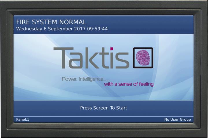
The Fire System Normal screen displays when the XT+ Extinguishant Control Panel is operating properly and indicates that the installation was successful. Determine that the Fire System Normal condition is visible on the panel GUI before initiating the Panel Tests. Fire System Normal condition is displayed following the booting cycle and occurs when trouble conditions are not reported.
|
|
Panel Tests
Panel Tests are provided through the No User Group of the panel GUI. No User Group contains a limited set of operations and does not require password authorization to initiate. The No User Group menu is immediately available for operation following the booting cycle.
Lamp & Buzzer Test
This test confirms operation of the indicator lamps and the buzzer. To perform the Lamp & Buzzer Test:
- Press the panel GUI during the Fire System Normal condition.
- Press Panel Tests and then Lamp & Buzzer Test. The internal buzzer of the fire control panel sounds and all indicator lamps light for 5 seconds. Contact Technical Support if fascia lamps do not light.
Display Test
Perform the Display Test to confirm operation of the panel GUI.
- Press the panel GUI during the Fire System Normal condition.
- Press Panel Tests and then Display Test. A confirmation window will appear.
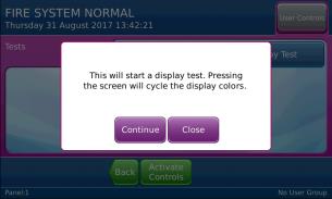
- Press Continue to test the display. The panel GUI cycles through a series of blank raster colors.
System Information
The System Information window includes details such as Software Version, File manager, LED Controller, I/O Board Controller, Configuration Manager, and the Event Log. View the System Information to determine the operating status of the XT+ Extinguishant Control Panel. To view system information on the XT+ Extinguishant Control Panel:
- Press the panel GUI during the Fire System Normal condition.
- Press System Information. Press More to display subsequent System Information windows.
Event Log
View the Event Log to determine the status of initiating devices, signaling line circuits, and notification appliances. To view the Event Log of the XT+ Extinguishant Control Panel:
- Press the panel GUI during the Fire System Normal condition.
- Press View Event Log on the User Controls window.
- Press More Details to display additional information about the posted event message.
Programming the Panel
The XT+ Extinguishant Control Panel can be configured in the following ways:
- Panel GUI using access level 3
- Loop Explorer 2 via computer (USB Type B) or USB flash drive (USB Type A).
Most features can be programmed using the panel GUI. However, some advanced features can only be programmed using the Loop Explorer 2 utility.
Loop Explorer 2
Many of the XT+ Extinguishant Control Panel features and settings can be configured using the program Loop Explorer 2 (LE2). Licenses can be obtained through your sales representative. The following features are configurable via LE2.
- SLC configuration, including SLC Detector sensitivity, SLC device input action, and SLC device delay.
- Zone settings (Alarm Verification, Pre-Signal, Positive Alarm Sequence)
- Network settings
- Common or Zonal Mode setting
- Panel Module settings
- Panel NACs
- Ring Mode options
- Maintenance date keeping
- Unique device labels (i.e., ALK-V can be renamed “APT 101 Bedroom 1”)
- Unique panel labels (i.e., Node 1 can be renamed “Building 10”)